Multi Wii Copter LCD Config
About
LCD_Config is a hardware and software solution to program the Multi Wii Copters on flying field, also it contains the possibility to log data while flying and playback the log files to the MultiWiiConf.
Features
- works for Multi Wii Software 1.5 (stable) and 1.6pre
- serial communication with the MultiWii software
- same parameters changeable as in the GUI
- presents sensor data (gyro, nunchuk, acc, barometer), receiver input channels, abd output channels (ESCs and servos)
- simple graphic output for servo channels and inclination angles
- logging to SD cards
- profile management to test different settings
Prerequisites
- an Arduino board Arduino Boards
- Arduino 022 (for SD Card support)
- a LC Display, either using parallel 4 Wires or ShiftReq control (based on the Hitachi HD44780 (or a compatible) chipset, which is found on most text-based LCDs.)
- Some keys, some cable
- latest Arduino Sketch for LCD_Config
Download
(Note: the version of the LCD_Config does not correspond to the version of the MultiWiiCopter software. All listed versions of the LCD_Config work with both MWC v1.5 and v1.6pre.)
V1.50: http://www.rc-heli-fan.org/download/file.php?id=92207
V1.60: http://www.rc-heli-fan.org/download/file.php?id=92263
V2.0 beta: http://www.rc-heli-fan.org/viewtopic.php?f=255&t=80336&start=315#p1186998
V2.0: http://www.rc-heli-fan.org/viewtopic.php?f=255&t=80336&start=375#p1190414
V2.1: http://www.rc-heli-fan.org/viewtopic.php?f=255&t=80336&start=420#p1193837
V2.2: http://www.rc-heli-fan.org/viewtopic.php?f=255&t=80336&start=450#p1197679
V2.3: http://www.rc-heli-fan.org/viewtopic.php?f=255&t=80336&start=480#p1201705
Version History
V0.8 to V1.4 see [1]
V1.50
- check trailing 'A' char in serial communication to detect frame errors,
- KEY_LEFT cancels reading when no serial connection is present (important to reset wrong settings!)
- optimization of format routines (merged two routines, invalid values are displayed as ###)
- bugfix in logging (logMode=-1 was stored in flash, so logging was permanently disabled)
V1.60
- Min/max values show up again (optional)
- Fixed some issues on compiling with different options
V2.0 beta
- Adaptation to MWC version 1.preter6 (new config "Flying Wing", new data format)
- Changed arrangement of parameters in state "0 - Config"
- Bug 'logMode=-1' finally solved
V2.0
- Swapped motors 4 and 5 in 'Esc Out' for versions 1.5 and 1.6prebis
- Changed behaviour of UP and DOWN for consistency (UP decrements, DOWN increments values)
- Added version V1.6
- Output logfiles in LogView format [OPTIONAL] (file numbers starting from 500, extension ".lvw")
- Added JOYSTICK option to replace input buttons by an analog joystick [experimental]
- Display 'invalid' values in graphics
- Heavy optimizations (!) due to space restrictions
- Removed WAIT_FOR_INIT option, changed start state to 31 instead
V2.1
- Bugfix in deserialize() with v1.6
- Joystick handling was improved (calibration, use of pullups, can be used in parallel to buttons)
- Added 'Play LogFile' state
- Easter egg function to display internal configuration :)
- BUGFIX: RC Rate multiplied by factor 2 for MWC Versions >v1.5, minimum of 20% for RC Rate (0% makes no sense)
- Added random offsets in TEST mode
V2.2
- Cancel in Logfile Playback (press LEFT_KEY)
- Settings of "Baud Rate", serialRead() has been adapted to work with different COM speeds
- Greater flexibility in changing the Settings
- (Log) Delay Time was moved to Settings state and is used as the time interval of polling the MWC board
Hardware
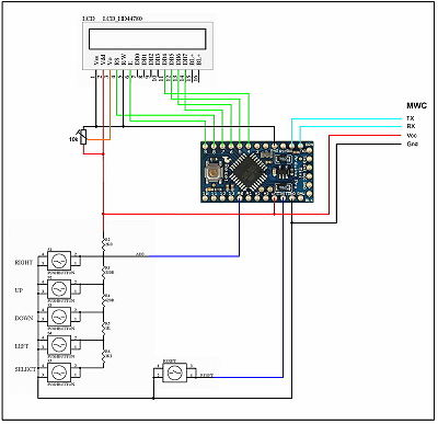
LCD Keypad Shield
This is the original LCD used with the LCD_Config app:
Schematics: http://www.nuelectronics.com/estore/index.php?main_page=project_lcd
Joystick
Emulation of the four required input buttons via an analog Joystick (like the one used in Wii Nunchuks). Requires two analog input pins and (optional) one digital or analog input pin for the Select key.
Hardware Keys
If you like to use normal hardware keys on digital ports use this schematic to connect them:
http://arduino.cc/en/Tutorial/DigitalReadSerial
Then remove the comment signs // in front of line:
#define HWKEYS
Define the ports to use here:
// Input pins of the hardbuttons: (used when HWKEYS is defined)
#define HW_RIGHT    10
#define HW_UP        9
#define HW_DOWN     11
#define HW_LEFT      8
#define HW_SELECT    6
It is possible to controll everything with out the Select key, so you don't need this key.
Shift Register LCD
Using 3 wires interface for the display:
http://www.arduino.cc/playground/Code/LCD3wires
Adjust the ports used here:
ShiftRegLCD lcd(3, 2, 4, 2); // (Datapin, Clockpin, Enablepin or TWO_WIRE [, Lines [, Font]]])
Logging
Connection of SD Card: standard SPI interface, i.e.,
pin 13   SCK   SPI clock
pin 12   MISO   SPI master in, slave out
pin 11   MOSI   SPI master out, slave in
pin 10   SS   SPI slave select
Logfiles are written either in binary format, in that way they can be sent to and visualized by the MultiWiiConf software, or (starting from Version 2.0) in LogView OpenFormat, to display them in LogView. A corresponding device file for LogView (.ini) is included in the archive beginning from Version 2.0. For more details, check out www.logview.info (and don't forget to donate :)).
Status LEDs
Primary goal of this option is to give some visual feedback on the internal state when no LCD is connected. Three LEDs are supported, named RED, YELLOW and GREEN (like a traffic light).
The red LED signals errors (slow flashing, e.g., when the application is halted), or recoverable exceptional states (fast flashing, e.g., the app is waiting for input from the serial connection).
Yellow LED: blinking means I/O, it is permanently on when the app is waiting for user input
The green LED signals logging.
LEDs are connected through 220-500 Ohm resistors to some of the unused ports (default: A1 - Red, A3 - Yellow, A5 - Green).
Port settings are defined here:
// include routines to show the state of the application with three leds
// (red: error, yellow: busy/waiting for input, green: logging)
#define STATUS_LEDS

#define RED_LED      A1
#define YELLOW_LED   A3
#define GREEN_LED    A5
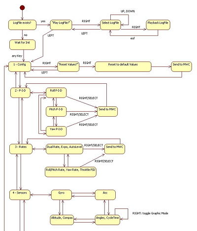
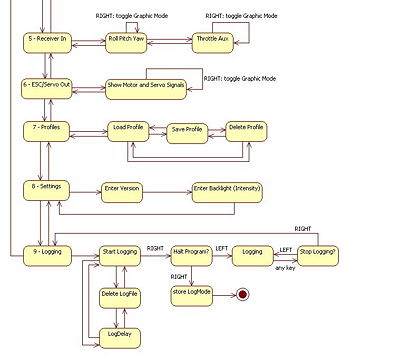
State chart
Gallery
Schematics as PDF,.PLT, Image
http://www.rc-heli-fan.org/viewtopic.php?p=1185353#p1185353
http://www.rc-heli-fan.org/viewtopic.php?f=255&t=80336&start=105#p1178184
http://www.rc-heli-fan.org/viewtopic.php?f=255&t=80336&start=120#p1180305
Here some links to already build and working boxes
http://www.rc-heli-fan.org/viewtopic.php?f=255&t=80336#p1166512
http://www.rc-heli-fan.org/viewtopic.php?f=255&t=80336&start=60#p1171774
http://www.rc-heli-fan.org/viewtopic.php?f=255&t=80336&start=60#p1171802
http://www.rc-heli-fan.org/viewtopic.php?f=255&t=80336&start=105#p1180155
http://www.rc-heli-fan.org/viewtopic.php?f=255&t=80336&start=120#p1180731
http://www.rc-heli-fan.org/viewtopic.php?f=255&t=80336&start=135#p1180893
http://www.rc-heli-fan.org/viewtopic.php?f=255&t=80336&start=135#p1181027
http://www.rc-heli-fan.org/viewtopic.php?f=255&t=80336&start=135#p1181131


